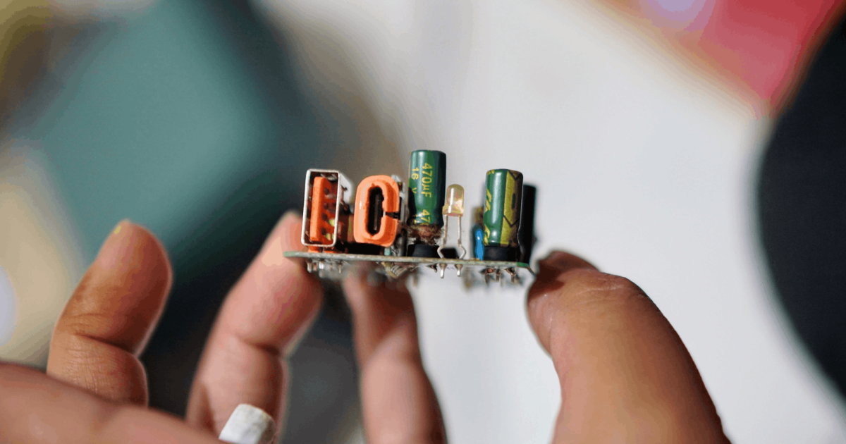


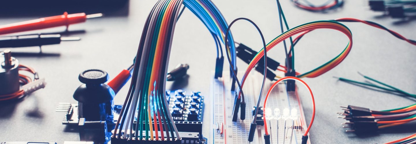
Making the transition from breadboard to PCB is one of the most consequential decisions in electronics prototype development. Move too early and you lock in design choices before the circuit is stable, burning NPI budget on respins. Move too late and you are validating behavior that a breadboard’s parasitic capacitance, inductance, and loose connections cannot accurately replicate at production signal speeds. The right timing is not a milestone you cross automatically. It is a deliberate engineering judgment based on circuit stability, signal integrity requirements, component footprint constraints, and the downstream cost consequences of each iteration.
TL;DR
- Breadboards are for early concept validation only; they are not a proxy for production electrical behavior [unitypcb.com]
- The decision to move to PCB should be driven by circuit stability, component type, and signal frequency, not by project timeline pressure
- Every unnecessary PCB respin adds cost and schedule risk to your NPI program
- PCB DFM decisions made at layout stage directly determine your unit cost at volume
- Transitioning with a structured workflow, including DFX analysis, significantly reduces late-stage engineering changes
What is the actual purpose of a breadboard in a modern prototyping workflow?
Before examining when to leave the breadboard behind, it is worth being precise about what a breadboard can and cannot do. A breadboard’s role is concept validation [pcbcart.com]. It lets you confirm that a circuit topology works in principle: that a sensor responds, a voltage regulator stabilizes, a microcontroller boots. What it cannot tell you is whether that behavior will survive at speed, under thermal load, across a PCB trace with real impedance characteristics, or in a mechanically constrained enclosure.
This distinction matters because engineers sometimes extend breadboard use past its useful life, treating it as a low-risk environment when the circuit has already moved beyond the questions breadboards can answer. At that point, the breadboard is not reducing risk. It is deferring the real validation work and building false confidence.
Practically speaking, breadboard use is appropriate when:
- The schematic is still being iterated at a component or topology level
- The circuit operates at low frequency (typically below 1 MHz) where parasitic effects are negligible [suntronicinc.com]
- Through-hole or large-format components are involved and the physical circuit fits the breadboard format
- The goal is behavioral confirmation, not performance characterization
Once you are characterizing timing, signal integrity, EMC behavior, or power efficiency, you need copper. A PCB is not a cleaner breadboard. It is a fundamentally different test environment [unitypcb.com].
When does staying on breadboard become a cost risk to your NPI program?
Building on the validation limits above, the harder question is what extended breadboard use actually costs you at the program level. The answer depends on what your circuit needs to prove and when it needs to prove it.
The clearest cost triggers for moving to PCB earlier rather than later are:
- SMD-only component dependencies: Surface-mount components cannot be used directly on standard breadboards. Adapter boards introduce their own parasitics. If your bill of materials (BOM) is dominated by SMD parts, breadboard fidelity collapses [pcbinq.com].
- Signal frequencies above 1 MHz: Breadboard wire connections and contact resistance distort high-frequency behavior. Measurements taken here will not transfer to the PCB [suntronicinc.com].
- Power distribution sensitivity: Breadboards share power rails across rows with non-trivial resistance. Circuits with tight supply decoupling requirements will behave differently on copper [everestcase.com].
- Tight component placement or thermal constraints: These can only be validated in layout, not on a breadboard.
Every week spent on breadboard iteration beyond these thresholds is a week not spent hardening the layout. And in NPI programs with fixed gate reviews, that time has a direct cost.
What engineering decisions at PCB layout stage most affect your unit cost at volume?
Stepping back from the timing question, a separate concern is what happens at the layout stage itself. This is where electronics design engineering decisions have the most direct effect on your downstream cost structure, and where they are most often made without enough manufacturing input [advancedpcb.com].
The critical layout decisions that determine unit cost include:
| Design Decision | Cost Impact at Volume |
|---|---|
| Component placement relative to test points | Drives ICT fixture cost and test coverage |
| Layer count selection | Directly determines bare board fabrication price |
| Via type (through-hole vs. blind/buried) | Buried vias increase cost significantly |
| Panelization approach | Affects SMT yield and depaneling scrap |
| Pad size and courtyard clearances | Influences paste deposit reliability and rework rate |
| Trace width and copper pour strategy | Impacts etch yield on fine-pitch designs |
The underlying principle is that DFM is not a review you run after PCB layout is complete. It is a set of constraints that need to be active during layout. DFM feedback at the end of a layout cycle almost always requires rework. DFM constraints embedded from the start are absorbed into the first revision [advancedpcb.com].
How should the breadboard-to-PCB transition be structured to reduce respin risk?
A related but distinct question is how you actually execute the transition in a way that minimizes the number of PCB iterations. The modern electronics prototype development workflow treats this as a structured handoff, not a single event [digitalmonk.biz].
A practical transition sequence looks like this:
- Freeze the schematic. No topology changes after the schematic is released to layout. Partial freezes create partial layouts and always require respin.
- Run DRC and ERC before layout begins. Electrical rule checks and design rule checks catch errors that are free to fix in schematic and expensive to fix in copper.
- Apply DFX constraints at layout entry. DFM, DFA, and DFT rules should be loaded into your layout environment before the first component is placed, not applied as a review afterward [pcbinq.com].
- Prototype in PCB, not breadboard iteration. Once you commit to copper, commit fully. Run a focused prototype build, not a phased breadboard-to-PCB hybrid.
- Validate against production intent. Your prototype PCB should be designed to the same panelization, layer stack, and material spec as your production intent. Test with the production process, not a one-off approach.
- Conduct a formal DFM review before releasing to manufacture. This should involve your manufacturing partner, not just internal design review.
The goal is not to eliminate PCB iterations entirely. Complex designs will require respins. The goal is to ensure that each iteration is planned, teaches something specific, and does not repeat mistakes that DFX analysis would have caught in software.
Season Group’s engineering teams engage on NPI programs from the concept stage because the breadboard-to-PCB decision and the early layout choices that follow it carry real cost consequences that compound across respins. With 50+ years of experience running PCBA builds across programs of varying complexity, early design decisions and their effects on production yield, test coverage, and unit cost are well understood. Customers who are working through prototype development often use the UK facility for quick-turn NPI builds before volume production is transferred to China, Malaysia, or Mexico, which means the DFM feedback loop stays close to the engineering process throughout.
Frequently Asked Questions
Q: Can I skip the breadboard phase entirely and go straight to PCB?
For simple, well-understood circuits with no novel topologies, yes. For new designs with unproven component interactions, skipping breadboard entirely increases respin risk. The decision depends on how much is genuinely unknown at concept stage [pcbcart.com].
Q: How many PCB prototype iterations should I expect?
Most hardware products require two to four prototype iterations before production release, depending on complexity. Structured DFX review at each stage is the most reliable way to reduce that number [digitalmonk.biz].
Q: What is the most common mistake engineers make when moving from breadboard to PCB?
Carrying breadboard schematic assumptions into PCB layout without revisiting them. Component values tuned on a breadboard often need adjustment on copper because the electrical environment changes [suntronicinc.com].
Q: Does DFM review apply to prototype PCBs or only production designs?
DFM applies to every PCB that will eventually scale. Running DFM on your first prototype means your second or third revision is already closer to production intent [advancedpcb.com].
Q: When should I involve my manufacturing partner in the PCB design process?
At the schematic stage, if volume production is the end goal. Manufacturing input at schematic review is low-cost. Manufacturing input at production release is high-cost [pcbinq.com].
Q: How does panelization affect my prototype cost?
Panelization configured for volume SMT production lowers per-unit cost at scale. Prototype panelization that differs from production intent means you are validating a process you will not use [everestcase.com].
Q: What certifications or standards should I design to for industrial PCB builds?
IPC-A-610 class defines the acceptance criteria for solder quality. IPC-2221 covers general PCB design. If your product targets aerospace or automotive, design to the quality system requirements of AS9100D or IATF 16949 from the start, as retrofitting later is expensive.
About Season Group
Season Group is a design and manufacturing partner with 50+ years of experience since 1975, operating a multi-site manufacturing network across China, Malaysia, Mexico, and the UK. The company supports electronics programs from early concept and NPI through volume production and lifecycle management, with integrated DFX engineering, PCBA, and full box build capabilities. Season Group works with OEMs and product companies across the industrial, power, access security, and automotive sectors, offering a single-partner model that connects design engineering decisions directly to production outcomes.
If your program is approaching the breadboard-to-PCB transition and you want a manufacturing-informed view of your layout before you cut the first board, visit https://www.seasongroup.com or email inquiry@seasongroup.com to talk through your requirements with our team.