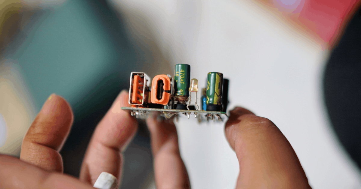


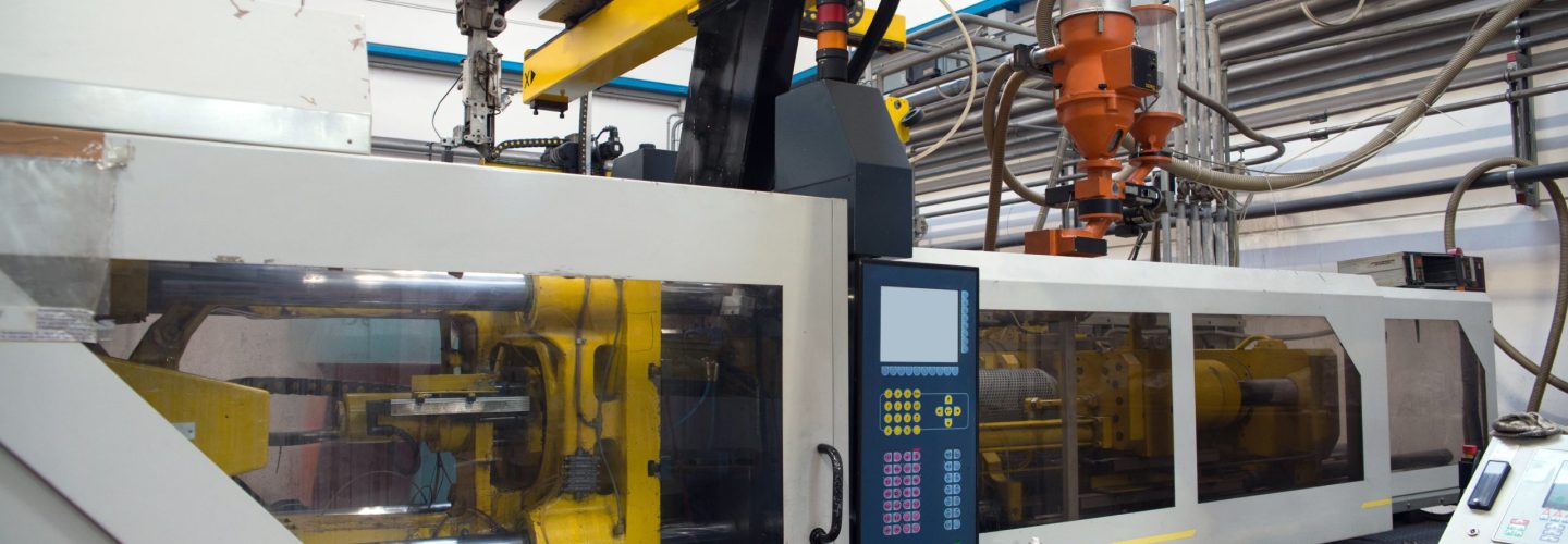
Combining plastic injection molding and PCBA production under one roof changes the engineering conversation fundamentally. When enclosures and the electronics inside them are made by the same team, tolerance decisions are no longer negotiated across organizational boundaries. Lead time compression becomes structural rather than incidental. The tradeoffs, however, are real: vertical integration demands disciplined DFM upfront, tighter cross-discipline communication, and a manufacturing partner with the process depth to make both sides of the build accountable to each other.
TL;DR
- Running injection molding and PCBA on the same production line eliminates the tolerance gaps that typically form when enclosures and electronics come from separate suppliers.
- DFM alignment across both disciplines must happen early, not after tooling is cut.
- Lead time reductions are achievable, but only when both process teams share constraints from the start.
- Vertical integration introduces its own risk: misaligned design reviews can propagate problems across both streams simultaneously.
- Choosing a partner with genuine depth in both processes matters more than geographic convenience.
About the Author: Season Group is a design and manufacturing partner with 50+ years of experience delivering integrated electronics and plastic manufacturing programs for industrial OEMs, access security manufacturers, and power product companies. Their China facility operates as a vertical integration center of excellence, running injection molding and PCBA under a single quality system.
What does “shared production line” actually mean for injection molding and PCBA?
A shared production line in this context does not mean physically adjacent machinery. It means that the injection molding team and the PCBA team operate under unified program management, shared DFM review cycles, and coordinated scheduling. The enclosure is not treated as a bought-out component delivered to the PCB assembly line. It is a co-developed output, subject to the same engineering gates.
This matters because the default procurement model treats the molded enclosure as a commodity input. The electronics team finalizes their board dimensions, connector placements, and mounting hole positions, then hands a drawing to a separate molder. That sequence creates one-way dependency: the board defines the enclosure, and the enclosure team has no early input on features like PCB standoff geometry, snap-fit tolerances, or thermal venting that affect both assembly and PCBA performance.
How does vertical integration change tolerance assumptions?
Building on that dependency problem, the tolerance implications are where vertical integration pays off most concretely. Injection molded parts carry inherent dimensional variation driven by material shrinkage, cooling rates, and gate location [rapiddirect.com]. When a separate supplier produces the enclosure, their stated tolerances rarely reflect worst-case variation across a production run. The PCBA team then designs to nominal, and field assembly problems appear later.
When both processes share a program, the molder’s actual process capability data informs the PCB layout and connector positioning from the start. Specifically:
- Shrinkage compensation is factored into PCB-to-enclosure clearance at design time, not discovered during first article inspection [protolabs.com].
- Draft angles on internal bosses and standoffs are set with the PCB mounting load in mind, not just ejection convenience [hubs.com].
- Parting line placement is negotiated to avoid interference with PCB seating surfaces or connector openings [sz-zuerst.com].
- Wall thickness consistency directly affects boss strength at mounting points, and that data should be in the hands of the mechanical and electronics engineers simultaneously [plasticsplus.com].
The practical result: tolerance stacks that would typically require an engineering change order after tooling is cut get resolved before the mold is designed. That is not a minor efficiency. Tooling changes are expensive and they reset lead time.
What do injection molding design guidelines look like when PCBA constraints are in scope?
Injection molding design guidelines typically focus on wall thickness uniformity, rib proportions, draft angles, and gate placement [fictiv.com]. When PCBA requirements are also in scope, those guidelines need to extend to cover:
- Boss geometry for PCB standoffs: Boss diameter and wall thickness must support the fastener torque used in PCBA assembly without cracking during reflow cooling cycles [blog.epectec.com].
- Connector cutout tolerances: Cutouts for USB, power, or signal connectors on the molded enclosure must account for both mold dimensional tolerance and the PCB connector’s positional tolerance after reflow.
- Internal clearance for conformal coating: If the PCBA will receive conformal coating, the enclosure interior needs clearance that accommodates coating thickness, particularly around snap-fit retention features.
- Thermal management features: Venting ribs or heat sink channels molded into the enclosure must be designed with knowledge of component placement and heat dissipation requirements from the PCBA team.
- Insert molding for EMI shielding: When metallic inserts are co-molded for grounding or EMI purposes, their position must correlate with PCB ground planes and shield can locations [protolabs.com].
Without PCBA input, these details get treated as secondary. With a shared program, they become first-class design requirements. This is where following integrated injection molding design guidelines, rather than separate discipline-specific ones, makes the difference between a clean NPI and a protracted rework cycle.
Where does lead time compression actually come from?
Lead time reduction under vertical integration is real but frequently overstated. The honest picture is that compression comes from three specific mechanisms, not from proximity alone.
1. Parallel tooling and board layout: When the enclosure design and PCB layout proceed concurrently under shared DFM governance, tooling lead time no longer sits in sequence after board finalization. Weeks can be removed from the critical path.
2. Shared first article and functional test: When the same team runs fit-check on the enclosure and functional test on the assembled PCBA, a single test event can validate both. Separate suppliers require two sequential sign-off cycles.
3. Reduced iteration cycles: Enclosure-to-board interface problems that would generate two to three rounds of supplier communication get resolved in one internal review. That matters more than it sounds: each external revision cycle typically adds one to three weeks.
What vertical integration does not compress: mold build time, SMT line scheduling, or component lead times. If a customer enters the program with an aggressive timeline but underspecified requirements, the efficiency of vertical integration is consumed by the added engineering cycles.
What are the genuine risks of shared-line vertical integration?
A related but distinct question is where the model fails, because it does fail in specific conditions. Vertical integration concentrates risk as much as it concentrates efficiency.
- Cross-contamination of problems: A design error caught late in the molding phase can simultaneously invalidate PCB layout work if both were proceeding in parallel. Separate suppliers would have contained the damage to one stream.
- Internal communication gaps: The same organizational boundary problems that exist between suppliers can exist between internal teams if program management is not disciplined.
- Process depth requirements: Running both injection molding and PCBA at production quality requires significant capital, equipment diversity, and a process engineering workforce that spans both disciplines. Not every manufacturer offering both services has genuine depth in both [injectionmoldschina.com].
The third point is the most practically relevant for buyers. Claiming both capabilities on a capability sheet is not the same as running both under a unified quality system with shared DFM governance.
Season Group’s vertical integration model reflects the realities above. The China facility runs injection molding across multiple tonnage ranges alongside automated SMT and full box build production, operating under a single quality and program management structure. With 50+ years of manufacturing experience and DFX embedded from NPI through production, the team routinely manages enclosure-to-board tolerance alignment, insert molding for functional integration, and parallel tooling and assembly scheduling within the same program. As a design and manufacturing partner, Season Group provides the structural integration that reduces the coordination overhead typically driving schedule risk in programs where the enclosure and electronics are not separable problems.
Frequently Asked Questions
Can injection molding and PCBA truly share DFM review cycles, or are the disciplines too different?
They can, and they should. The shared review focuses on interface geometry: boss positions, connector cutouts, PCB clearance, and thermal features. Each discipline still runs its own internal checks, but the interface review is where vertical integration adds the most value.
What tolerance should I expect at the enclosure-to-PCB interface on a shared-line program?
This depends on material, geometry, and wall thickness, but shared programs allow the molder’s actual process capability to inform PCB layout tolerances directly rather than relying on nominal stated values. Expect tighter real-world fit than a dual-supplier model at comparable complexity.
Does vertical integration make sense for low-volume programs?
It makes more sense than most buyers assume, because the benefit is iteration speed and DFM quality, not just per-unit cost. For NPI programs with tight schedules, the engineering alignment is valuable even at low volumes.
How does parting line placement affect PCBA assembly?
Parting lines can leave witness marks or minor flash that interferes with PCB seating or connector insertion if not located carefully [sz-zuerst.com]. On a shared program, parting line position is confirmed against assembly drawings before tooling is approved.
What certifications should a vertically integrated manufacturer hold for both disciplines?
ISO 9001 covers both, but sector-specific requirements vary. IATF 16949 applies to automotive programs. AS9100D applies to aerospace. IPC-A-610 governs PCBA inspection class. A manufacturer should be able to show applicable certification for each discipline, not just for the facility as a whole.
Does running both processes in-house reduce per-unit cost?
Sometimes. The cost benefit depends on volume, tooling amortization, and whether the program would otherwise require significant inter-supplier coordination overhead. Cost reduction is a possible outcome, not a guaranteed one.
What happens when a program needs to transfer to another site after development?
With standardized processes across a multi-site network, transfer is more straightforward than in a custom one-off setup. The DFM documentation, tooling data, and test protocols travel with the program, provided the original program was built to transferable standards.
About Season Group
Season Group is a design and manufacturing partner with 50+ years of experience supporting electronics OEMs from early design through full-scale production. Operating a manufacturing network across China, Malaysia, Mexico, and the UK, the company provides integrated PCBA, plastic injection molding, wire harness assembly, and DFX engineering services under a unified quality framework. Season Group works with industrial, access security, power, and automotive customers building products where enclosure and electronics performance are inseparable.
If your program involves enclosure-electronics integration and you want to work through the tolerance and scheduling assumptions early, visit https://www.seasongroup.com or reach out to us at inquiry@seasongroup.com to talk through your requirements with our team.